Fundamentals of Leak Detection
- Introduction
- Types of Leaks
- Leak Rate, Leak Size, (Gas) Mass Flow
- Terms and Definitions
- Leak Detection Methods Without a Leak Detector
- Leak Detectors and How They Work
- Specifications for Leak Detectors and Limit Values
- Leak Detection Techniques Using Vacuum Leak Detectors
- Industrial Leak Test
Introduction


In addition to the actual vacuum pump systems and their individual components (vacuum vessel, lines, valves, measuring devices, etc.), there are numerous other systems and products in the fields of industry and research with high requirements regarding tightness or so-called "hermetic sealing". These include, in particular, assemblies for the automotive and refrigeration industries as well as many others.
Generalized statements often made, such as “no detectable leaks” or “leak rate zero”, do not represent an adequate basis for acceptance testing. Every experienced engineer knows that properly formulated acceptance specifications will indicate a certain leak rate under defined conditions. The acceptable leak rate is also determined by the application itself.
Types of Leaks
The simplest definition for the term "leak" is an "opening" in a (separating) wall or barrier through which solids, liquids or gases can undesirably enter or exit. The following leak types are differentiated depending on the type of material or joining fault:
- Leaks in detachable connections: Flanges, ground mating surfaces, covers
- Leaks in permanent connections: Bending, solder and welding seams, glued joints
- Leaks due to porosity: Particularly following mechanical deformation (bending) or thermal processing of polycrystalline materials and cast components
- Thermal leaks: Opening up of leak due to extreme temperature loading (heat/cold)
- Apparent (virtual) leaks: Quantities of gas will be liberated from hollows and cavities inside cast parts, blind holes and joints (also due to the evaporation of liquids)
- Indirect leaks: Leaking supply lines in vacuum systems or furnaces (water, compressed air, brine)
- "Serial leaks": This is the leak at the end of several "spaces connected in series", e.g. a leak in the oil-filled section of the oil case pan in a rotary vane pump
- "One-way leaks": These will allow gas to pass in one direction but are tight in the other direction (very seldom). An area which is not gas-tight, but which is not leaky in the sense that a defect is present would be the same
- Permeation: Naturally permeability of gas through materials such as rubber hoses, elastomer seals, etc. (unless these parts have become brittle and thus "leaky")
Leak Rate, Leak Size, (Gas) Mass Flow
No vacuum system or device can ever be absolutely vacuum-tight, nor does it actually need to be. The essential element is the leak rate must be low enough that the required operating pressure, gas balance and ultimate pressure in the vacuum container are not influenced. The leak rate of a vessel indicates the amount of gas flow which escapes through the walls of the vessel. It must be noted, however, that the leak rate for a leak depends on the type of gas.
If the desired ultimate pressure is not reached in a vacuum system, there are usually two causes for this: the presence of leaks and/or the gas liberation from the vessel walls and seal outgassing.
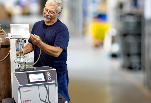
In order to differentiate between the two causes, a partial-pressure analysis with a mass spectrometer or the time-related pressure rise test may be used. Since it is only possible to determine the existence of a leak and not its position in the system when using the pressure rise test, it is recommended to use a helium leak detector so that leaks may also be localized significantly faster.
The Helium Standard Leak-Rate is required for the unequivocal definition of a leak and the pressures prevailing on either side of the (vessel) wall and the nature of the medium passing through that wall (viscosity, molar mass).
For the case where the test is carried out with helium mass 4 at a pressure difference of 1 bar from the atmosphere pressure (external) to the vacuum (p < 1 mbar, internal), which is frequently found in practice, the designation "helium standard leak rate" has been introduced. In order to indicate the rejection rate for a test using helium under standard helium conditions, it is necessary first to convert the real test conditions of use to helium standard conditions.
Terms and Definitions
When searching for leaks one will generally have to distinguish between locating leaks and measuring the leak rate in addition to the direction of flow for the fluid. There are a couple of methods that are widely recognized:
a. vacuum method (sometimes known as an "outside-in leak"), where the direction of flow is into the test object; the pressure inside the test object is less than ambient pressure.
b. positive pressure method (often referred to as the “inside-out leak”), where the flow takes place from inside the test object outward; the pressure inside the test object is higher than the ambient pressure. The test objects should wherever possible be examined in a configuration corresponding to their later application, i.e. components for vacuum applications using the vacuum method and using the positive pressure method for parts which will be pressurized on the inside.
When measuring leak rates, we differentiate between registering individual leaks (local measurement) and registering the total of all leaks in the test object (integral measurement). The smallest leak rate which is no longer tolerable in accordance with the acceptance specifications is known as the rejection rate. Its calculation is based on the condition that the test object may not fail during its planned utilization period due to faults caused by leaks, and this to a certain degree of certainty.
Often it is not the leak rate for the test object under normal operating conditions which are determined, but rather the throughput rate of a test gas under similar conditions. The achieved measuring values have to be converted to correspond to the actual application situation in regard to the pressures inside and outside the test object and the type of gas (or liquid) being handled.
Where a vacuum is present inside the test object (p < 1 mbar), atmospheric pressure outside, and helium mass 4 is used at the test gas, one refers to standard helium conditions. Standard helium conditions are always present during helium leak detection for a vacuum system when the system is connected to a leak detector. If the system is pumped down too p less than 1 mbar and if it is sprayed with helium mass 4, one refers to the spray technique.
If the test object is evacuated solely by the leak detector, then one would say that the leak detector is operating in the direct-flow mode of the leak detector (LD).
If the test object is itself a complete vacuum system with its own vacuum pump and if the leak detector is operated in parallel to the system’s pumps, then one refers to partial-flow mode of the leak detector. One also refers to partial-flow mode when a separate auxiliary pump is used parallel to the leak detector.
When using the positive pressure method, it is sometimes either impractical or in fact impossible to measure the leakage rate directly while it could certainly be sensed in an envelope which encloses the test specimen. The measurement can be made by connecting that envelope to the leak detector or by accumulation (= increasing the concentration) of the test gas inside the envelope (see Fig. 4c). The bombing test is a special version of the accumulation test.
In the so-called sniffer technique, another variation of the positive pressure technique, the (test) gas issuing from leaks is collected (extracted) by a special apparatus and fed to the leak detector. This procedure can be carried out using either helium, refrigerants, SF6 as the test gas.
Leak Detection Methods Without a Leak Detector
The most sensible differentiation between the test methods used is the differentiation as to whether or not special vacuum chamber leak detection equipment is used. In the simplest case a leak can be determined qualitatively and, when using certain test techniques, quantitatively as well (this being the leak rate) without the assistance of a special leak detector.
For example, the quantity of water dripping from a leaking water faucet over a certain period of time can be determined by collecting the water with a measuring vessel. In this case, however, one would hardly refer to this as a leak detector.
In spite of careful inspection of the individual engineering components, leaks may also be present in an apparatus following its assembly – be it due to poorly seated seals or damaged sealing surfaces. The processes used to examine an apparatus depend on the size of the leaks and on the desired degree of tightness as well as on whether the apparatus is made of metal, glass or other materials.
There are a few general vacuum leak detection methods used in accordance with the particular application situations (sometimes limited by economic factors):
- Pressure rise test - capitalizes on the fact that a leak allows in a quantity of gas
- Pressure drop test - the exact opposite of the pressure rise test
- Leak test using vacuum gauges which are sensitive to the type of gas
- Bubble immersion test - rising gas bubbles indicate leaks in a submerged-in-liquid testing scenario
- Foam-spray test - escaping gas forms soap bubbles at the leak points
- Vacuum box check bubble - similar to foam-spray, but bubbles are trapped to examine flat surfaces
- Krypton 85 test - a radioactive isotope to measure pressure
- High frequency vacuum test - electrical gas discharge can indicate pressure inside equipment
- Test with chemical reactions and dye penetration
Leak Detectors and How They Work
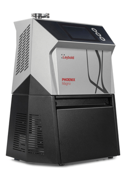
Most leak testing today is carried out using special leak detection devices like vacuum leak detectors. These can detect far lower leak rates than methods that do not use special equipment. The function of most leak detectors is to conduct testing with a special test gas, i.e. with a medium other than the one used in normal operation.
Halogen Leak Detectors and Halogen Diode Principle
Equipment operating in accordance with the halogen diode principle can also detect SF6. Consequently, these sniffer units are used to determine whether refrigerants are escaping from a refrigeration unit or from an SF6 type switch box (filled with arc suppression gas).
Leak Detectors with Mass Spectrometers (MS)
It is possible to detect all gases using mass spectrometry. Of all the available options, the use of helium mass 4 as a test gas has proved to be especially practical. Every mass spectrometer consists of three fundamental assemblies: ion source, separation system and ion trap.
Detection Limit, Background, Gas Storage in Oil (Gas Ballast), Floating Zero-Point Suppression
The smallest detectable leak rate is dictated by the natural background level for the test gas to be detected. Even with the inlet at the leak detector closed, test gas will enter the mass spectrometer and will be detected there if the electronic means are adequate to do so. The background signal generated in the mass spectrometer determines the detection level of the leak detector. In general, the more test gas is present in the oil the higher the background signal of the leak detector will be.
In the case of "dry leak detectors", which are leak detectors without oil-sealed vacuum pumps, the problem of gas storage in the oil does not exist. However, dry leak detectors must still be flushed with gas which is free of test gas since, over time, test gas will accumulate in these devices as well.
In order to spare the user, the trouble of always having to keep an eye on the background level and simplify the operation of the leak detector, the “floating zero-point suppression” has been integrated into the automatic operating concepts of all Leybold leak detectors.
Independent of the floating zero-point suppression, Leybold leak detectors offer the capability for manual zero point shifting. Here, the display for the leak detector at the particular moment will be reset to zero so that only rises in the leak rate from that point on will be shown.
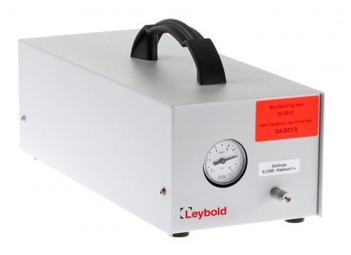
Calibrating Leak Detectors; Calibration Leaks
The calibration of a leak detector is to be understood as the adjustment of the display at a leak detector, to which a calibration leak (or test leak) is attached. A calibration leak is a leak whose leak rate at a certain temperature and under specific pressure conditions is known precisely.
Leak Detectors with Quadrupole Mass Spectrometer
Leak detectors with quadrupole mass spectrometers (QMS) are mostly built to detect masses greater than helium mass 4. Apart from special cases, these will be refrigerants or lamp filling gases - leak detectors with QMS are mostly used to inspect refrigeration units for leaks.
Leak Detectors With 180° Sector Field Mass Spectrometer
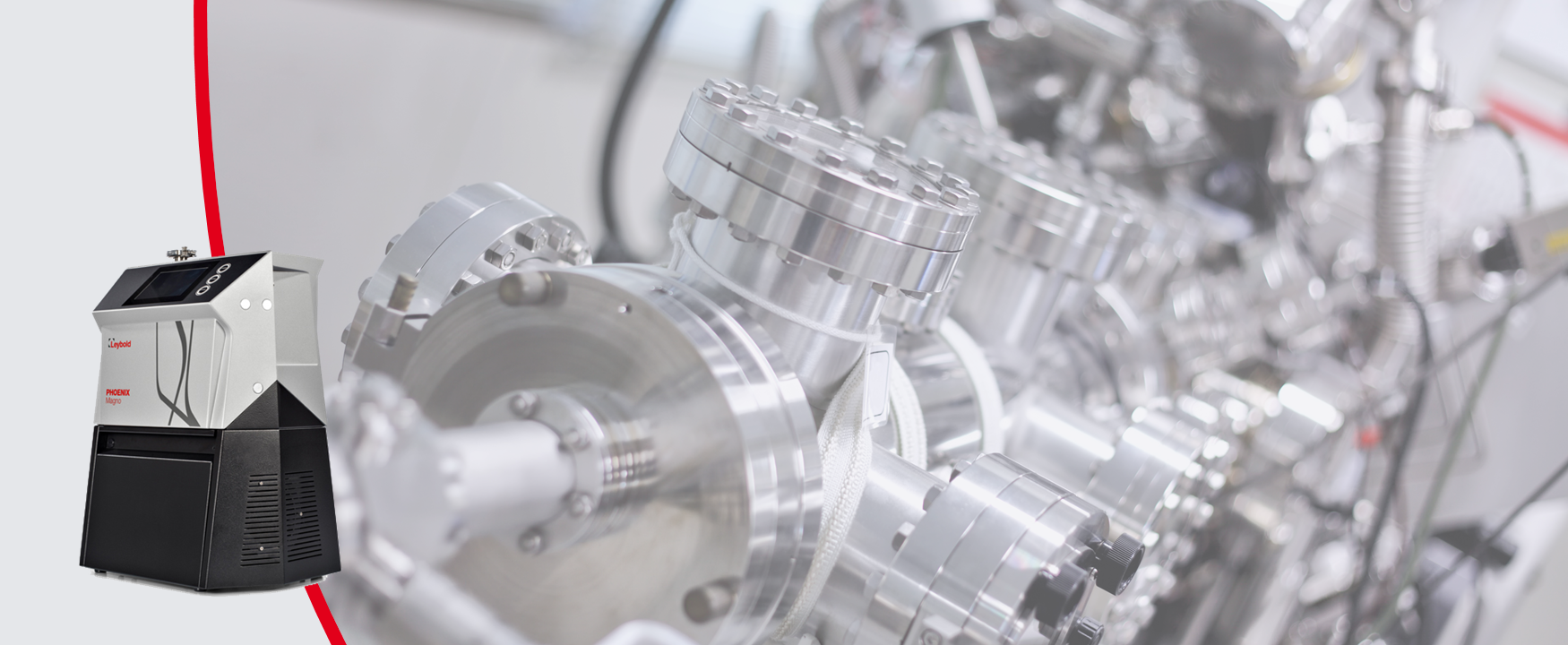
Helium leak detectors with 180° sector field mass spectrometer are the most sensitive and reliable leak detection devices. There is no other leak detection method with which one can, with greater reliability and better stability, locate leaks and measure them quantitatively. Therefore, helium leak detectors, even though the purchase price is relatively high, are very economical in the long run since the required for the leak detection procedure itself is very short.
Direct-Flow and Counter-Flow Leak Detectors
Depending on the way in which the gas from the test object is supplied to the mass spectrometer, one can differentiate between the two types of helium leak detectors: the direct-flow leak detector and counter-flow leak detector.
In both cases, the mass spectrometer is evacuated by a high-vacuum pump system. In case of the direct flow leak detector, the gas to be inspected is supplied to the mass spectrometer via a cold trap. The cold trap is cooled with liquid nitrogen (LN2) and is basically a cryopump in which all the vapors and other contaminants condense.
Counter-Flow Leak Detector in Partial-Flow Operation
If evacuating the test object to the required start pressure is impossible or takes too long due to the size of the test object or the leak, an auxiliary pump (auxiliary pump system) must be used in addition to the leak detector.
Connection to Vacuum Systems
The connection of a leak detector to vacuum systems with multi-stage vacuum pump sets is usually carried out by means of the partial-flow method. When considering where to best make the connection, it must be kept in mind that the leak detector is usually a small, portable unit which has only a low pumping speed at the connection flange (typically with pumping speed of 3m3/hr).
Specifications for the Leak Detector and Limit Values
1. The smallest detectable leak rate (qLmin)
2. The effective pumping speed for the test gas at the inlet (Seff, TG)
2a. The effective pumping speed for air at the inlet (Seff)
3. The maximum permissible pressure inside the test object (pmax)
(= the maximum permissible inlet pressure)
The maximum permissible inlet pressure pmax is about 10–1 mbar for leak detectors with classic turbomolecular pump and 2 to 15 mbar for leak detectors with a compound turbomolecular pump.
4. The maximum permissible gas flow for air (qmax)
The product of the maximum permissible inlet pressure pmax and the effective pumping speed for air at the inlet Seff equals the maximum permissible gas flow for air qmax. If a gas flow which is greater than qmax enters the leak detector due to one large or several small leaks, the device is inoperable.

Leak Detection Techniques Using Vacuum Leak Detectors
Vacuum Method – Spray Technique (Local Leak Test)
The test object connected to the vacuum leak detector is traced with a very fine stream of test gas from the spray pistol at likely leakage points (flange connections, welding seams, etc,) in an appropriately slow manner. The appropriate speed for this process is determined by the response time of the system. The test gas amount sprayed must be adjusted to suit the leak rate to be detected as well as the size and accessibility of the object being tested.
Positive Pressure Method – Sniffer Technique (Local Leak Test)
The test object is filled with test gas to an extent so that the partial test gas pressure in the test object is significantly larger than that around the test object. The likely leak positions of the test object are traced with a sniffer tip in an appropriately slow manner. A typical tracing speed is 1 cm/s.
Envelope Test According to the Positive Pressure Method
This method makes it possible to detect even the smallest overall leakage and is suitable in particular for automated industrial leak testing. When the test object, pressurized with helium, is placed in a rigid vacuum vessel which is connected to a helium leak detector, the integral leak rate can be read directly at the leak detector.
Envelope Test According to the Vacuum Method
The evacuated test object which is connected to the leak detector is enclosed with a flexible, light (plastic) envelope. Before the envelope is filled with helium, one presses it against the test object, in order to remove as much of the existing atmosphere air as possible. The entire outer surface of the test object has contact with the test gas (helium). If test gas enters the test object through the leaks, the integral leak rate is measured without knowing the exact number of leaks.
In case of repeated tests in closed rooms, it must be noted that the helium concentration in the room will increase rather rapidly after removing the envelope. Using plastic bags is therefore more advisable for "one-time testing" of large systems.
Rigid envelopes should be used in case of test series for determining integral leak rates. Furthermore, this has the advantage that the helium can be recovered after the test has been carried out.
"Bombing" Test, "Storage Under Pressure"
The "bombing test" is used to check the tightness of components which are already hermetically sealed, and which exhibit a gas-filled, internal cavity. The components to be examined e.g.
- IC housings
- transistors
- laser diodes
- reed contacts
- quartz oscillators
are placed in a pressure vessel which is filled with helium. Operating with the test gas at relatively high pressure (5 to 10 bar) and leaving the system standing over several hours the test gas will accumulate inside leaking test objects. This process is called "bombing.”
Industrial Leak Test
Industrial leak testing using helium as the test gas is characterized above all by the fact that the leak detection equipment can be fully integrated into the manufacturing line. The design and construction of such test units will naturally take-into-account the task to be carried out in each case:
- leak testing of car rims for tubeless tires and fuel tanks
- leak testing of components for refrigeration and air conditioning technology
- leak testing of metal drums
where mass-produced, standardized component modules will be used wherever possible.
There are several advantages of industrial leak testing using helium as test gas:
- The detectable leak rates are significantly lower than the leak rates which must be detected in practice
- The integral leak test also allows for the detection of microscopic and sponge-like distributed leaks
- The testing procedure and testing sequence can be automated
- The cyclical, automatic test system check ensures great testing reliability
- Helium is non-toxic and non-hazardous
- The quantitative results of the test can be documented quickly and easily along with all process parameters
Additional Leak Detection Resources:
The complete fundamentals of leak detection guide
Leak detection webinar for process industries
Endpoint detection
The do's & don'ts of leak detection
Shop leak detection instruments
Leybold, a member of the globally active industrial Atlas Copco Group of companies, has developed into the world market leader in the area of vacuum technology. In this leading position, we recognize that our customers around the world count on Leybold to deliver technical superiority and maximum value for all our products and services.
To us, partnership-like customer relationships are a fundamental component of our corporate culture as well as the continued investments we are making in research and development for our next generation of innovative vacuum technology products.
In the course of our over 165 year-long corporate history, Leybold developed a comprehensive understanding of process and application know-how in the field of vacuum technology. Jointly with our partners and customers, we plan to continue our efforts to open up further markets, implement new ideas and develop pioneering products.
Leybold GmbH


